Shock Mounted, Forward Facing, Catchers Mask Propeller Guard Invention
Our Shock Mounted, Forward Facing, Catchers Mask Propeller Guard invention disclosure below was posted on 15 August 2011. We will make no changes to the text below line following this paragraph except to correct misspellings, punctuation, and to update html/computer codes and links. Any updates to the invention will be posted below the invention disclosure.
Shock Mounted, Forward Facing, Catchers Mask Propeller Guard Invention
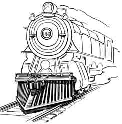
Many cage type boat propeller guards focus on preventing people from contacting the propeller, not on moving people out of harm’s way. They form a nice physical barrier around the propeller with little regard for the damage that the barrier itself may cause to those struck while moving forward.In contrast, early day locomotive trains used cowcatchers to knock cows and debris off the railroad tracks. They tried to lift and direct livestock, debris, and wild animals struck up, to the sides, and off the tracks. Many modern locomotives still have a remnant of a cowcatcher on front to help clear the rails.
I once had the opportunity to see an escaped cow I was chasing on foot through a small town face down an oncoming train. The train was passing through town at a modest speed. The engineer had no chance of stopping before it hit her and was blowing the train whistle trying to scare her off the tracks. She was either knocked off the tracks, jumped to the other side at the last fraction of a second, or both. Whatever happened, she had no visible injuries.
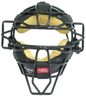
Another contrasting example, modern day catchers masks present a rounded front to oncoming baseballs or softballs. They are also shock mounted (see all the padding between the mask and the catcher’s face) to reduce the loads felt by catchers when their mask is hit by a ball or bat and to better fit the mask to an individual catcher’s face.
As a high school catcher I took many tipped pitches (foul balls just barely tipped by the batter) on the face mask and a few bat strikes. They certainly got your attention, but caused no injuries.
On the other hand, many cage type propeller guards taper to present a vertical leading edge, just slightly wider than the leading edge of the outboard or stern drive.
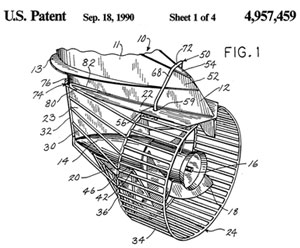
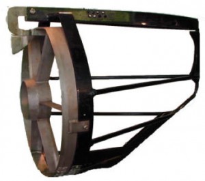
When viewed from a rear quarter, several cage type guards taper towards the front where they follow the knife-like vertical contour of the leading edge of the drive and skeg. Richard Snyder’s/Mercury Marine’s propeller guard and Robert (Bob) Hooper’s Prop Buddy propeller guard shown above are examples of cage type propeller guards that taper forward to the leading edge of the drive. Their sharp vertical leading edge presents no more danger than the existing leading edge of the drive. However, designers fail to take the opportunity to present a blunter, more cowcatcher / catchers mask profile shape that distributes the force of impact over a broader area (reducing local stresses / lacerations / cuts) while more gently moving the person or marine life out of the way of the oncoming propeller.
Propeller guard designers probably hug the leading edge of the drive is to increase rigidity, durability, and reduce vibration. Near similar results can be obtained by using rubber-like bushings/dampers/shock cushions that fit between the current sharp “V” of the leading edge of the drive and the wires/rods of the guard that pass in front of the leading edge of the drive. The shock cushions could be preformed to fit snugly against the drive behind them and accept the wires/rods in front of them. They would allow a more rounded catchers mask profile to the front of the guard while still maintaining considerable stiffness and strength, and providing shock absorption.
Humans and marine life can suffer blunt trauma when hit by boats, marine drives, or propeller guards above certain speeds. Water is much denser and more viscous than air. As result, water provides much greater resistance to movement than air. Bodies struck in water must also move some volume of water surrounding them out of the way as they move. This additional water is often called added mass or virtual mass. Some suggest that you move about half as much more water than your body or limb displaces when struck by a propeller guard. Added mass is a major contributor to blunt trauma because it greatly increases the resistance of the human body to movement when struck by a boat, marine drive, or propeller guard.
The boating industry has sometimes said that blunt trauma injuries from propeller guard strikes become a major factor at about 10 miles per hour and increase in severity with increasing boat speeds, depending on the design of the propeller guard design.
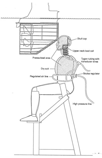
| The knife-like leading edge on guards we discussed earlier can also be seen in the old 1990 SUNY tests of the Snyder guard. During those tests, Mercury Marine, a Brunswick company, and OMC (Outboard Marine Corporation) ran the pointed leading edge of the guard right at the bend to the skeg into foreheads of underwater crash dummies strapped in chairs. Needless to say, they caused considerable damage. This image is from the SAFE Journal Vol.24 No.3 which published a paper on those tests. |
Summarizing to This Point
Okay, so far we have established that:
- Some cage type guards have sharp, vertical leading edges that follow the contour of the leading edge of the drive.
- Those sharp vertical leading edges (looks like a “V” cross section when viewed from above) can injure humans and marine life.
- Humans and marine life struck by boats, marine drives, or propeller guards may suffer blunt trauma injuries, especially when struck at speeds in excess of 10 miles per hour.
- The risk and severity of blunt trauma injuries to humans and marine life continues to increase as boat speed increases.
- Catchers masks are shock mounted to reduce the impacts felt by catchers when the mask is hit by a ball or bat.
What are the Alternatives?
How can we prevent or mitigate these injuries to humans and marine life?
Among the many alternatives, three come quickly to mind:
- Blunt/round the leading vertical edge of the propeller guard to look more like a catchers mask to spread the load over a broader area of the person or marine life being struck.
- Contour the front of the guard (the portion that extends rearward to form a cylindrical section around the propeller) in a manner that pushes people or marine life out of the way instead of slicing them.
- Absorb some of the shock of impact with deformable materials or shock absorbers to lessen blunt trauma injuries to humans and marine life.
Georgia Tech and Georgia Department of Natural Resources (DNR) have been using artificial turtles (full scale engineered models of turtles) in boat and propeller guard impact tests searching for ways of improving turtle survivability from such impacts. We recently wrote up their testing in an article titled, Boat and Propeller Guard Strike Tests Model Turtles But Not People.
Similar tests could be used to test strikes by the leading edges of propeller guards and aid in optimizing the designs. We are just talking about making the leading edge viewed from above that is now “V” shaped, more “U” shaped. The additional flattening of the leading edge should not effect overall drag because the resulting wires/rods would still have the same projected area when viewed from the front.
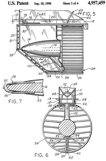
| Dick Snyder’s guard is typical. It tightly grips the leading vertical edge of the drive, then even adds a vertical single wire as seen in Patent Figure 7 at left.
One way to reduce blunt trauma and lacerations from the Snyder guard is to round/flatten the vertical cross sectional of the guard as seen in Patent Figure 7. If the leading edge was at least a few inches wide, while still being rounded, any leading edge impacts would be distributed over more area, and result in less cutting and tearing. Additionally, vertical edge leading wire (#32 in Figure 7) could be either welded back in the same plane as a series of short pieces (so it would not be a sharp leading edge itself, OR formed into the guard before it was bent into shape. Either of these approaches would result in a blunter, flatter, rounder vertical leading edge, that more evenly distributes impact loads, and thereby reduces injuries. |
Adding Shock Absorption
Just like a catchers mask, the entire guard could be mounted on resilient rubber-like shock absorbers allowing the guard to move a little with impact, decreasing maximum accelerations felt by humans and marine life struck by the guard.
For example, another alternative for the Snyder Guard above would be to put the vertical edge leading wire (#32 in Figure 7) behind the plane of the horizontal wires. This method might also make it easier to fit the shock bushings between the leading edge of the drive and the guard. When viewed from the top, the back side of the shock bushing would have a “V” cut from it to accept the leading edge of the drive. When viewed from the front, the front side of the shock bushing would have cross cut from it to accept the horizontal and vertical wires/rods of the propeller guard. The shock bushing would be streamlined and of minimal profile when viewed from the front to reduce drag.
It is well known that the use of elliptical wires/rods in propeller guards presents a smaller cross section to oncoming flow and reduces drag. Shock bushing could easily be formed to accept elliptical wires as well.
Yet another alternative would be to construct a cage type prop guard in a minimum of at least two sections. An independent front face section could be shock mounted to the rest of the guard and/or drive.
But there is an easier way, especially on smaller, lighter drives.
Adding Shock Absorption via Trim Cylinder Trail Out
Outboards and stern drives sometimes strike underwater floating logs, strike bottom, or other obstacles. Without some means of allowing the drive to swing up and over the obstacle the drive might actually be ripped off the transom. Most trim cylinders contain relief valves in the piston itself that allow the cylinder rod to extend if the drive hits something. Many also contain a “memory piston” that stays put when the drive swings up and over something. Gravity soon forces the drive back down. Fluid from between the memory piston and the cylinder piston goes back through check valves in the cylinder piston as it flows back to the rod side of the cylinder. This allows the trim cylinder piston to retract back against the memory piston and the boat continues safely on its way.
The system described above that allows the drive to swing out, up, and over obstacles struck at speed is sometimes referred to as the log strike system. Tests of the system are called log strike tests.
In May 2010, Teleflex was issued U.S. Patent 7,722,418 for “Energy Dissipation Valves for Hydraulic Cylinders”. The Teleflex patent focuses on the design of relief valves used in trim cylinders. Currently most trim cylinder relief valves use springs constants of about 200 to 400 pounds per inch. Manufacturers preload (compress) the springs to get a high cracking pressure before the relief valve begins to open.
Teleflex switches the loads. They suggest use of a stronger spring (near 875 pounds per inch) with a lighter preload. Their design also includes stop that prevents the valve from fully opening until the pressure builds up to similar values as the existing design. Low preload (minimal compression) allows the Teleflex relief valves to start opening (cracking) at much lower pressures. This allows them to dissipate energy from much lower impacts (slower collisions) than competing designs.
Relatively slow moving boats can hit submerged objects and come to an instant stop because the impact did not generate enough pressure to activate the relief valves of existing designs. Many people have been ejected in these situations placing them at risk of being struck by the boat, struck by the propeller, and drowning.
The Teleflex design appears to offer “cushioning” to objects, people, and at least to larger marine life (manatees, dugongs, dolphins, whales, etc.) struck in the water at slower speeds (the drive will begin to swing up at much lower pressures). While the Teleflex design still needs further testing for this application, we suggest it may be able to significantly raise the threshold of blunt trauma injuries from beginning at 10 miles per hour (per the industry) to a much higher speed, especially for smaller drives.
Larger drives have more inertia, and testing remains to be done to show how for up the size range (horsepower, weight of the portion of the drive that trims up and down) will allow this approach to be effective. We anticipate the maximum size (horsepower or weight) may also be different for different manufacturers based on their models (groups of drives on the same frame), two stroke vs. other technologies with different weights per horsepower, and geometry of attachment of the drives.
We originally suggested this approach on August 17, 2007, in the form of two old Brunswick patents (U.S. Patent 3,999,502 and 4,050,359). The two old Brunswick patents focus on allowing an orifice to bleed flow from the rod end of the trim cylinder, allowing the rod to extend when objects are struck at slower speeds. Brunswick said their design could be made economically and reliably, and had a long operating life. They called the practice, trim cylinder trail out.
References
- Our previous 17 July 2007 post on our Propeller Guard Technologies page in which we identified the Brunswick trim cylinder trail out valves as possible blunt trauma limiting devices.
- Potential Blunt Trauma Solution: Trim Cylinder Trail Out. Our report, Houseboat Propeller Guard Injury Avoidance Measures Proposed and Withdrawn by the U.S. Coast Guard. Page 135. Propeller Guard Information Center. June 15, 2010.
- U.S. Patent 4,050,359 and U.S. Patent 6,176,170 examples of trim cylinder log strike systems including relief valves, check valves, and memory pistons.
- Boat and Propeller Guard Strike Tests Model Turtles But Not People. Propeller Guard Information Center. August 7, 2011.
- Circle of Death posting on our <2011 Propeller Safety Technologies page dated 24 July August 2007.
- Circle of Death Propeller Accident Invention. Propeller Guard Information Center. June 17, 2010.
Our Claims
We (Polson Enterprises and the Propeller Guard Information Center) claim the the propeller safety invention described above and now make a public disclosure of it and place all parts of it not previously patented by others into the public domain for use by all who wish to manufacture or use them. The world is certainly welcome to patent improvements to this invention but the basic concepts not previously patented by others are open to all.
More specifically we claim:
1. The use of blunted, rounded leading edges on propeller guards as they pass generally horizontally in front of the vertical leading edges of outboards and stern drive legs and or skegs when used in conjunction with shock mounting of a least a portion of the font facing section of the propeller guard. That shock mounting may be in the form of traditional shock mounts, resilient mountings, traditional shock mounts or resilient mountings built into the propeller guard, or achieved by using a trim cylinder log strike shock system designed to provide shock absorption to humans and marine life.
2. A blunted, rounded leading edged propeller guard as described in #1 above in which the forward facing profile of the propeller guard resembles a catchers mask in terms of being rounded to the front.
3. The use of shock mounts or resilient mountings in the attachment of propeller guards, or portions or segments of propeller guards to marine drives as a means of dissipating loads to humans or marine life when struck by propeller guards.
4. The use of deformable materials in the construction of propeller guards as a means of dissipating loads to humans or marine life when struck by propeller guards.
5. The use of smart materials in the construction of propeller guards as a means of dissipating loads to humans or marine life when struck by propeller guards.
6. Use of outboard, stern drive, or other marine drive trim cylinder log strike shock systems designed to swing back at considerably lower pressures than current systems as a means of limiting blunt trauma and other injuries to people and marine life struck by propeller guards. For example, use of the technologies described in U.S. Patents 3,999,502, U.S. Patent 4,050,359, and U.S. Patent 7,722,418 in conjunction with a cage type, ring type, or other types of propeller guards.
7. Use of specifically designed trim cylinder log strike systems that allow a marine drive to swing back at considerably lower pressures than current systems as a means of increasing the maximum boat speeds at which people and marine life can survive blunt trauma injuries from cage type, ring type, or or other types of propeller guard strikes. For example, use of the technologies described in U.S. Patents 3,999,502, U.S. Patent 4,050,359, and U.S. Patent 7,722,418 in conjunction with a cage type, ring type, or other types of propeller guards.
Updates
Future updates to this invention will be posted here.
